Monday, January 18, 2021
Change the SSID of GeneXis Router
Login to the modem by typing the address 192.168.1.1 in the chrome address bar
Select the menu "net" from the top panel.
Click on the SSID to change the Ssid to new one

Tuesday, March 13, 2018
Adding Hidden wireless (wifi) to Raspberry Pi3
Open the wpa-supplicant configuration file using editor
sudo nano /etc/wpa_supplicant/wpa_supplicant.conf
Add the following line to the bottom of the file
network={ ssid="ssid name"
psk="Password"
}
If you are using a hidden ssid then add one more line
network={
    ssid="yourHiddenSSID"
    scan_ssid=1
psk="Your_wifi_password" }Tuesday, March 6, 2018
Using Serial Port - Rx Tx in Raspberry Pi 3
To use Rx Tx pin in Raspberry Pi...
In "/boot/config.txt" edit the last line enable_uart=1
Now use /dev/ttyS0 instead of /dev/ttyAMA0
Friday, November 10, 2017
Thursday, November 9, 2017
ESP8266 --posting data
Steps
AT+CIPSTART="TCP","WWW.KNRAPACHALLOOR.COM",80
AT+CIPSEND=61
GET http://www.knrapachalloor.com/my.php?dat=9 HTTP/1.0
Wednesday, November 8, 2017
PIP install
Adding the path of your pip installation to PATH system variable.
By default, pip is installed to
so the path "C:\Python27\Scripts" needs to be added to your PATH variable.
To add the path of your pip installation to your PATH variable, goto command prompt and type
By default, pip is installed to
C:\Python27\Scripts\pip (pip now comes bundled with new versions of python),so the path "C:\Python27\Scripts" needs to be added to your PATH variable.
To add the path of your pip installation to your PATH variable, goto command prompt and type
setx PATH "%PATH%;C:\Python27\Scripts" Restart the command prompt Wednesday, July 5, 2017
error - problem connecting to Raspberry Pi 3 with xrdp
sudo apt-get install tightvncserver
will do the task
Tuesday, May 17, 2016
USBPUSH for sending image files to ARM9
Error: No such file or Directory while executing ./usbpush
This error occurs when trying to execute a 32 bit binary from 64 bit OS
This error occurs when trying to execute a 32 bit binary from 64 bit OS
|
To install the 32-bit version, run:
|
Saturday, January 23, 2016
Raspberry Pi Display on LAPTOP
After a long search , finally I succeeded in getting the Raspberry Pi output on my Lap Top. Thanks to "Instructables"

Steps

- Download DHCP Server for Windows DHCP Download
- Change the properties of the Ethernet and set a fixed IP
- Run the DHCP Server Wizard (dhcpwiz.exe)
- Select the Ethernet adapter from the list
- Run DHCP server on a network card in which DHCP Disabled
- Click ->Next->Next->Finish
- Run the DHCP server now (dhcpsrv.exe)
- Click Continue as tray button
- Boot and connect the Ethernet cable to Raspberry Pi
- A popup will show the IP address assigned by the DHCP server to the Raspberry

- Now you can connect using the Remote desktop connect explained in the last post to see the Raspberry Pi Desktop on your laptop
 |
| Open Network & sharing |
 |
| b) Click on Change Adapter settings |
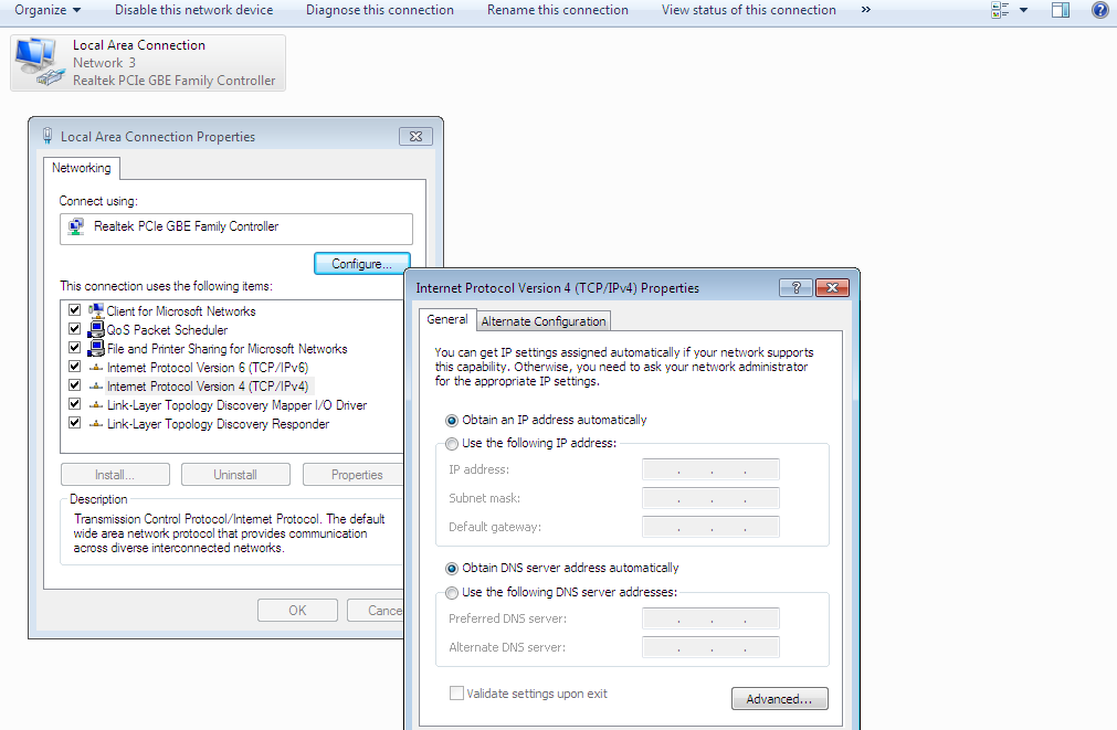 |
| Set a fixed IP Eg:192.168.2.2 |

Friday, November 13, 2015
Raspberry Pi
Setting up SSH in Raspberry Pi
Steps
1)To use SSH, first you need your Pi’s IP address. Boot your Pi to the command line and type:
sudo ifconfig
You can see "inet addr " 192.168.x.x
2)Download putty to Your PC
3)Open putty and type the IP address of the Raspberry and enter
4)PUTTY will open a terminal window which will prompt you for your username and password. of raspi
User Name: pi
Password:Raspberry
Remote Desktop for Your Raspberry Pi
1) 1)On your Raspberry Pi’s command line, (or with SSH), type:
sudo apt-get install xrdp
2) Open Remote Desktop Client on your PC (Its installed with Windows)
Start-All Programs-Accessories-Remote Desktop Connection

3) Enter the IP address when prompted.A xrdp window will pop up, prompting you for your username and password.
Monday, July 1, 2013
L293D: Extra cover
IC L293D , is the Motor Driver IC, which is usually
linked to Robotics Applications. Even if you tend to use this guy, few basic
questions still arouse in the minds of budding Hobbyists; Like Why 2 supply
pins on the IC, How much voltage can be given to the IC, Should I short all the
Ground pins of the IC ??????
Here, I'll be explaining the Pin description of
L293D and not the specifications or other technical details. You can refer
datasheet for that. L293D datasheet click here.
To start with, any Microcontroller development Board
works with a Max. of 5V, with a few hundreds of mA current. In case of ARDUINO
Duemilanov:
DC Current per I/O: 40mA
DC Current for VCC & GND: 200mA
Is this current sufficient enough to drive a
everyday 12V, 200RPM DC motor ?
No.
So what ?
Use a Motor Driver.
Does it help ?
Yes. It converts low current to high, sufficient to
drive a motor.

Pin Conections (Important: Even pro's tend to make
mistake here)
Pin 1 & 9:
Pin 1 is Enable 1. Used for enabling working of
Motor1 (IN1, IN2, OUT1, OUT2)
Pin 2 is Enable 2. Used for enabling working of
Motor2 (IN3, IN4, OUT3, OUT4)
Pin 2, 7 & 10, 15:
Inputs for Motor.
If pin 2 is +ve, pin 7 is -ve then motor Rotates in
one direction. If Pin 2 is -ve, pin 7 is +ve then motor rotates in reverse
direction.
Same explanation valid for Pin 10, 15.
Pin 16:
This is the Logic supply voltage for L293D. It
should not exceed 7V (recommended rating). But can go Max. upto 36V.
Pin 8:
This is the Output supply voltage. We can give upto
36V (Max), depending on our output voltage requirement.
So, this explains why there are two supply pins on
the IC. Pin 16 is usually provided for logic inputs to minimize the device
power dissipation.
Pin 4, 5, 12, 13:
These pins are ground pins. They form an on-board
Heatsink. Usually these pins are to be shorted
& connected to ground. But, I insist, take a multimeter and test the
connectivity of these pins. THEY ARE INTERNALLY SHORTED. We need not short them
again, it'll only increase the wire-do of your circuit.
Please remember that Pin 8 & 16 are totally
different. "Pin 8 is supply for left side, Pin 16 is supply for right
side" is WRONG.
Sunday, June 30, 2013
Keil-Project-Setup-for-STM32F4-discovery
ST Microelectronics provides a rich firmware support with its Discovery Promotion Kits. Its easy to modify the example codes to customize an application. However, here i am trying to explain, How to setup Keil MDK ARM Project for stm32f4 Discovery.
Step 1 : Open latest version of Keil uVision 4 ARM MDK IDE, Older version do not list stm32f407vgt6 device.

Make a New uVision Project Goto Project->New uVision Project
Step 2 : Save the project using a suitable name. You need a few libraries to work with STM32F4 or any other ARM Cortex Family. I recommend you to download the standard STM32F4 board support package provided by ST Micro. This BSP has all the necessary library including CMSIS and board specific drivers. Download STM32F4 Discovery BSP here.
Step 3: Extract the stm32f4 discovery bsp package on your local disk. You will find 3 major directories as Libraries, Project and Utilities. We are going to use Libraries and Utilities in further steps. Project directory contains various example projects, but we will be making our own project, still we need Libraries and Utilities directory as it is. So keep these two directories as it is and Make a new folder inside Project directory for new Project.

Save your project within a folder inside Project folder
Step 4 : Choose the Device as STM32F407VG. Keil will ask you whether to copy Startup.s into new project or not. Choose Yes here.

Choose the device as STM32F407VG

Choose Yes when it asks to include Startup.s into the Project
Step 5 : You may have various Source Groups in one project. By default only a single Source group is there, I prefer to make separate source groups each for User sources, MDK codes like StartUp.s and other for other libraries like Third party libraries, Board specific drivers.

Different Source Groups (Optional)
Step 6 : Add your own code e.g. main.c into User Codes source group. Add other files into different source groups as shown in figure below.
 Almost all the stm32f4 projects require these files named
stm32f4xx_it.c, stm32f4xx_it.h
system_stm32f4xx.c,
stm32f4xx_conf.h,
and misc.c.
Add these 5 files in Other source group as shown in figure above.
Now we are ready to perform some setting in the Project options section.


 What all those paths in Include Paths section of C/C++ Tab? Well these are the location of files, which your project compilation depends on. So here is a list of directories that you must include as path in your Keil Project fir stm32f4 Discovery.
- Libraries\CMSIS\Include
- Libraries\CMSIS\ST\STM32F4xx\Include
- Libraries\STM32F4xx_StdPeriph_Driver\inc
- Libraries\STM32F4xx_StdPeriph_Driver\src
- Utilities\STM32F4-Discovery
- The Project folder itself, which has main source code and stm32f4xx_it.c, system_stm32f4xx.c etc.

Include Paths in C/C++ Tab under Project Options
We are almost done, now try to build your project. Do not forget to add any required source file as explained in Step 8 . Any issues in compilation ? Comment below !
Saturday, June 29, 2013
Getting Started with the STM32F4 and GCC
Courtesy to: http://jeremyherbert.net/get/stm32f4_getting_started
Overview of this guide
This guide explains how to get a fully working ARM-GCC toolchain working under Ubuntu Linux, and provides makefiles that are specifically targeted towards the STM32F4 series of microcontrollers. Unfortunately, to load the code on the board, a windows computer (or VM) is needed. I am investigating linux based tools but I am yet to get one working.
One important aspect of this guide is that the compiler is built with hardfloat support. One of the major features of the ARM Cortex-M4 series is the hardware acceleration of floating point operations; however, most free toolchains and compilers don’t provide support for it (you need to cough up some dough for the non-free compiler).
Assumed background
Assumed background
To follow this guide, you should already know how to navigate and run commands within the linux terminal. Commands will look like this:
$ apt-get moo
means put “apt-get moo” in your favourite terminal software (or any terminal software really…). You should also know some basic C programming.
A special note for those who have not previously used ARM microcontrollers
Most microcontroller systems have very tight integration between the CPU and the on-chip peripherals due to the manufacturer designing and producing both subsystems. In the case of ARM-based microcontrollers though, a company namedARM Holdings designs the core and licenses it to manufacturers like ST (or NXP, Apple, Samsung, Qualcomm, HP, etc). This means that the manufacturer can spend time on making the on-chip peripherals powerful and reliable while ARM deals with things like power efficiency and instruction set design. On top of this, if the manufacturer follows the CMSIS guidelines, porting software between chips from different manufacturers is a piece of cake. Although peripheral use can be a touch more complicated than in a microcontroller developed completely by one manufacturer, using ARM-based microcontrollers is a much more cost-effective solution if you need high clock speeds and low power (YMMV, of course).
Stage 1: Build a Toolchain
Our build environment will be based on Ubuntu 11.10, so if you don’t already have itgrab the Ubuntu ISO now and install it on a PC or in a virtual machine.
The toolchain we will be using is a modified version of Summon-Arm-Toolchain. Summon-Arm-Toolchain is a shell script which downloads, builds and installs a fully working ARM toolchain for the Cortex-M3 (nice!). On top of this, the amazingMikeSmith has already performed the necessary modifications to build for the Cortex-M4 with hardfloat support with no extra work on our end (double nice!). To get started, we need to install all of its dependencies:
$ sudo apt-get install git zlib1g-dev libtool flex \
bison libgmp3-dev libmpfr-dev libncurses5-dev libmpc-dev \
autoconf texinfo build-essential libftdi-dev
Astute readers will note that a few of these aren’t listed as dependencies on the Summon-Arm-Toolchain page. I am not sure why. All of these are essential for building the toolchain.
Once that is complete, let’s clone the Summon-Arm-Toolchain repository:
$ git clone https://github.com/MikeSmith/summon-arm-toolchain.git
Now enter the directory and start the build process:
$ cd summon-arm-toolchain
$ ./summon-arm-toolchain
This will take a while, so go take a nap.
Once this is complete, add the “~/sat/bin” directory to your path. I did this by adding the following line to my ~/.profile file:
export PATH=$PATH:/home/jeremy/sat/bin
You can reload the file by running the command:
$ . ~/.profile
Check if it works by running the following command:
$ arm-none-eabi-gcc --version
And if you see something like,
arm-none-eabi-gcc (Linaro GCC 4.6-2011.10) 4.6.2 20111004 (prerelease)
Copyright (C) 2011 Free Software Foundation, Inc.
This is free software; see the source for copying conditions.  There is NO
warranty; not even for MERCHANTABILITY or FITNESS FOR A PARTICULAR PURPOSE.
you have an ARM toolchain capable of building binaries for the Cortex-M4!
Stage 2: Uh, so what do I do now?
It’s time to start writing some code! If you are at all familiar with embedded development, you might be familiar with the Microcontroller Programming Paradigm(tm):
1. Decide what peripheral you want to use
2. Look in datasheet for the registers to enable and configure it
3. Set bits in the registers to make peripheral behave the way you want
4. GOTO 1
In the case of the STM32F4, the datasheet has very little information on which registers to use. You can find it all tucked away in ST’s RM0090: STM32F4xx Advanced ARM-based 32-bit MCUs Reference Manual. There is also some information on the features of the ARM core in the ARM Cortex-M4F Technical Reference Manual. Finally, ST have published UM1472: STM32F4 High-Performance Discovery Board User Manual which tells you how devices are connected together on the board. Make sure you have these three saved somewhere so you can refer to them later.
Stage 2A: Building a Blinky
Note: This section asks you initially to compile code that is syntactically correct but functionally incorrect. This is intentional; I am hoping to demonstrate the sort of traps that you can fall into when developing for these chips. If you get easily frustrated, consider reading the whole section before compiling anything yourself.
To start a project from scratch, the first thing we normally do is work out how to use the compiler to compile our code. Unfortunately, it’s a little complicated and so for now we will be jumping straight to the code writing stage. To do this, we will be using my stm32-template project. So the first thing we need to do is get a copy of it:
$ mkdir ~/stm32_code
$ cd ~/stm32_code
$ git clone git://github.com/jeremyherbert/stm32-templates.git
Once the cloning is complete, take a look in the directory. You should find two directories, both of which contain a template build environment for two different ST development kits. Since we are working with the F4, we obviously want the “stm32f4-discovery” template. So let’s copy it to a new place so we can use it:
$ cp -r stm32-templates/stm32f4-discovery blinky
Now let’s have a look at the directory structure of the template project:
inc/
lib/
src/
Makefile
stm32_flash.ld
The
inc/ folder is there for you to put your *.h files in. Likewise, the src/ folder is for your *.c files. The lib/ folder is where we store all of the support files that ST have provided for the STM32F4 family of microcontrollers; you shouldn’t need to change anything in here, but have a look if you are curious. The Makefile instructs the makecommand on how to build our project (more on this later) and the stm32_flash.ldfile tells the compiler how to arrange the compiled information.
Before we start writing code, we need to clean up the template. It is set up by default to build the IOToggle example from ST, but we would much prefer to write our own code. So from
blinky/, run the following commands to remove the files we are not interested in:$ rm inc/stm32f4xx_it.h src/stm32f4xx_it.c src/main.c
$ touch src/main.c
Now we need to change
Makefile to tell the compiler we are only compiling main.c. Change this:SRCS = main.c stm32f4xx_it.c system_stm32f4xx.c
to this:
SRCS = main.c system_stm32f4xx.c
Ah, now we have a nice clean build environment.
Stage 2B: Actually writing some code, for reals this time
Let’s now open up
src/main.c and set it up for some serious C coding:
main-1.c:
1
2
3
4
5
6
| #include "stm32f4xx_conf.h"int main(void){ } |
Now let’s start at step 1 of the Microcontroller Programming Paradigm(tm) and look up how to control the GPIOs (General Purpose Input/Output) on the STM32F4. Looking in the contents, we can see that the GPIO-related information starts on page 136 in section 6, so open up your reference manual to that page and have a quick glance through. If you are used to 8 bit microcontrollers, you might be surprised as to how much more complex these chips are.
If you have decided that it looks too complicated and don’t want to continue, try watching this video. Otherwise, let’s open up the document to the GPIO register listing (section 6.4/page 148). Read the whole thing if you like, but we will cheat for now and I will tell you that the registers we are interested in are
GPIOx_MODER andGPIOx_ODR which will set the set the direction and output value respectively.
To set
GPIOx_MODER, let’s take a look at the table. There are 16 pins on each GPIO output port, so 16 two bit groups are used to configure the pin direction. Looking through the description below the table, it should be clear that we want “01: General purpose output mode” so we can turn the LED on and off. But which bit-pair do we want? The answer is in the STM32F4-Discovery User Manual (see above for the link), in section 4.4/page 16. It says:User LD3: orange LED is a user LED connected to the I/O PD13 of the STM32F407VGT6.
The PD13 means that we want pin 13 of GPIOD and thus we want MODER13; the 13th pair slot. Or to put it another way, we want the 26th bit of
GPIOD_MODER to be 1. Let’s put that in our code:
main-2.c:
1
2
3
4
5
6
| #include "stm32f4xx_conf.h"int main(void){ GPIOD->MODER = (1 << 26); // set pin 13 to be general purpose output} |
If you have done a bit of microcontroller programming before, you might be surprised to see the “->” (otherwise known as the structure dereference operator) in the left half of the new statement. We use it because ST organises registers by defining them as structures. Looking at
stm32f4xx.h should make more sense:
stm32f4xx-truncated.h:
1
2
3
4
5
6
7
8
9
10
11
12
13
14
15
16
17
18
19
20
21
| /* Lots up here */typedef struct{ __IO uint32_t MODER; /*!< GPIO port mode register, Address offset: 0x00 */ __IO uint32_t OTYPER; /*!< GPIO port output type register, Address offset: 0x04 */ __IO uint32_t OSPEEDR; /*!< GPIO port output speed register, Address offset: 0x08 */ __IO uint32_t PUPDR; /*!< GPIO port pull-up/pull-down register, Address offset: 0x0C */ __IO uint32_t IDR; /*!< GPIO port input data register, Address offset: 0x10 */ __IO uint32_t ODR; /*!< GPIO port output data register, Address offset: 0x14 */ __IO uint16_t BSRRL; /*!< GPIO port bit set/reset low register, Address offset: 0x18 */ __IO uint16_t BSRRH; /*!< GPIO port bit set/reset high register, Address offset: 0x1A */ __IO uint32_t LCKR; /*!< GPIO port configuration lock register, Address offset: 0x1C */ __IO uint32_t AFR[2]; /*!< GPIO alternate function registers, Address offset: 0x20-0x24 */} GPIO_TypeDef;/* Lots in between */#define GPIOD ((GPIO_TypeDef *) GPIOD_BASE)/* and heaps more down here too */ |
Given that the registers are located sequentially in memory, this structure simply maps the registers to human readable names.
So now that we know how to use registers, let’s turn on and off the LED using the ODR register (and a XOR trick).
main-3.c:
1
2
3
4
5
6
7
8
| #include "stm32f4xx_conf.h"int main(void){ GPIOD->MODER = (1 << 26); // set pin 13 to be general purpose output while (1) GPIOD->ODR ^= (1 << 13);} |
Now if you build this code, you can load it onto your device using the ST-LINK Utility under a Windows VM/system. Unfortunately though, it won’t work.
Stage 2C: Enabling peripheral clocks
Over the last half-decade, dramatically lowering current draw has been a goal for most microcontroller manufacturers. One of the techniques used to achieve this is to switch off on-chip peripherals by removing access to their master clocks. On the STM32 devices, these clocks are known as the hardware and peripheral clocks and are controlled by the RCC (Reset and Clock Control) group of registers. Since there are more than 32 on chip peripherals, there are actually two registers used to switch on a clock:
RCC_AHB1ENR and RCC_AHB2ENR (for the Hardware clock, APB for thePeripheral clock). The clock is controlled by set/reset registers, so to turn a system on you set a bit in the ENR register, and to turn that same peripheral off you set the bit in the corresponding RCC_AHBxRSTR register. Go and have a read of the register descriptions now, they start on page 93 (section 5.3) of the STM32F4 Reference Manual. To switch GPIOD on, we do something like this:
main-4.c:
1
2
3
4
5
6
7
8
9
10
| #include "stm32f4xx_conf.h"int main(void){ RCC->AHB1ENR |= RCC_AHB1ENR_GPIODEN; // enable the clock to GPIOD GPIOD->MODER = (1 << 26); // set pin 13 to be general purpose output while (1) GPIOD->ODR ^= (1 << 13);} |
Other on-chip systems use the peripheral bus, so be careful when checking whether you are using
AHB or APB registers. You are only one keystroke away from a well hidden bug.
You should also notice the register define I used to set the bit. ST has kindly written out human-readable names for each bit in configuration registers. The pattern should be fairly obvious:
__
Now our code is ready for primetime! Load it up on the chip and you will see…
…nothing.
Subscribe to:
Posts (Atom)